If you are new to Arm development, it is recommended to follow this short tutorial and learn how to build a simple test executable program that will blink a LED. You do not need any physical hardware for this, the test uses an emulated STM32F4DISCOVERY board.
Prerequisites
Before creating a new project, please be sure you checked all prerequisites described in the Prerequisites page, including the need to install the build tools if you use Windows as your development platform.
It is also recommended to set the workspace preferences and to install the desired CMSIS packs.
Create a new C++ project
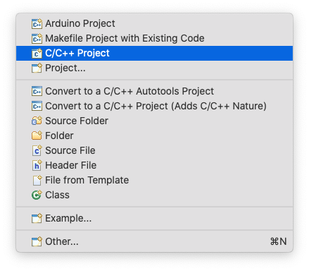
To create a new project, go to Eclipse menu, File → New (or the button in the upper left corner), and select the C++ Project:
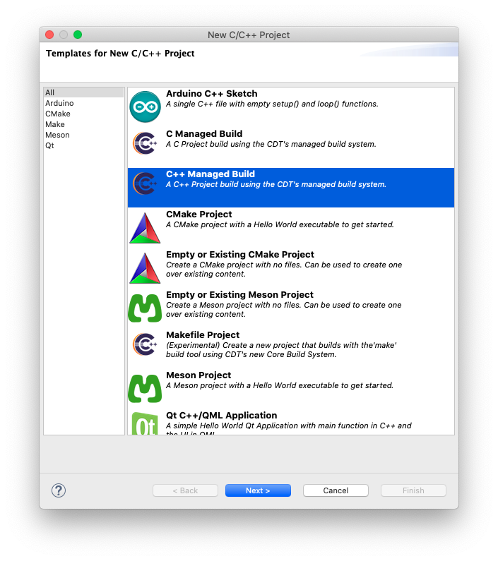
In the New C/C++ Project window, select C/C++ Managed Build and click the Next > button.
In the C++ Project window:
- in the Project name: field enter the name of the new project, for example blinky
- in the Project type: section expand the Executable type and select STM32F4xx C/C++ Project
- in the Toolchains: section select Arm Cross GCC
- click the Next > button

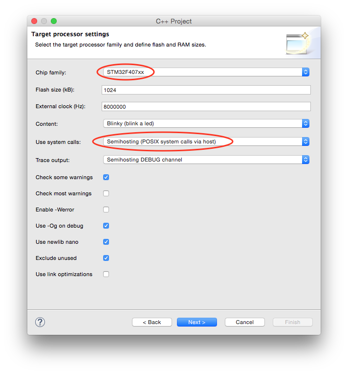
In the Target processor settings window be sure to:
- select the STM32F407xx chip family
- set the Flash size (kB) field to 1024 kB
- set the Clock (Hz): field to 8000000
- for a more complete example, change the Use system calls: fields to Semihosting (POSIX system calls via host)
- click the Next > button.
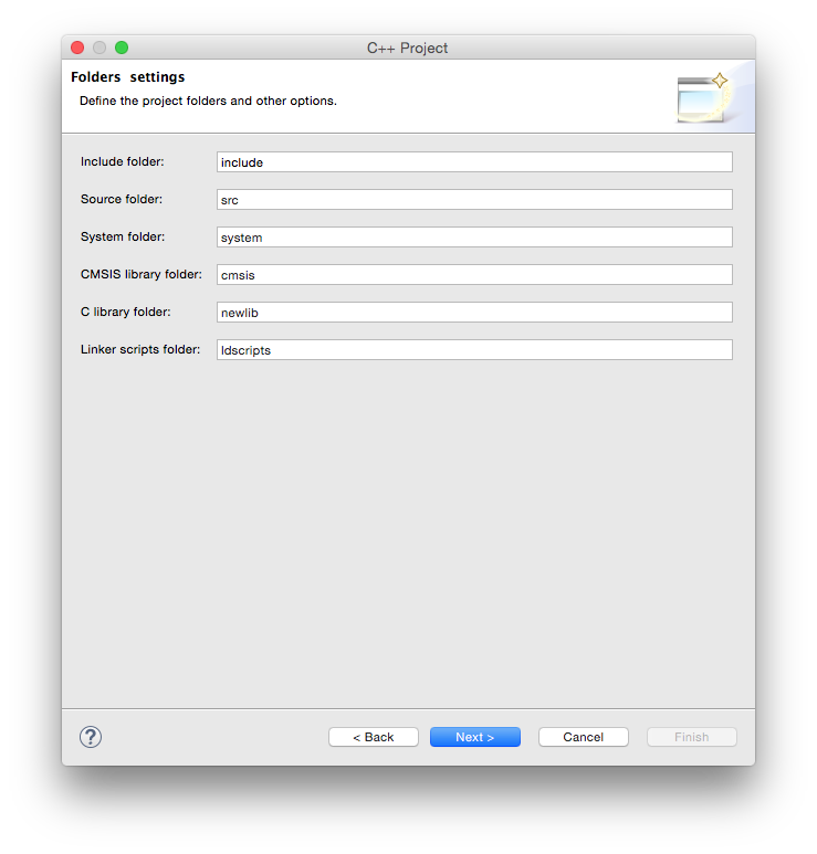
In the Folders page leave the suggested folders unchanged and click the Next > button.
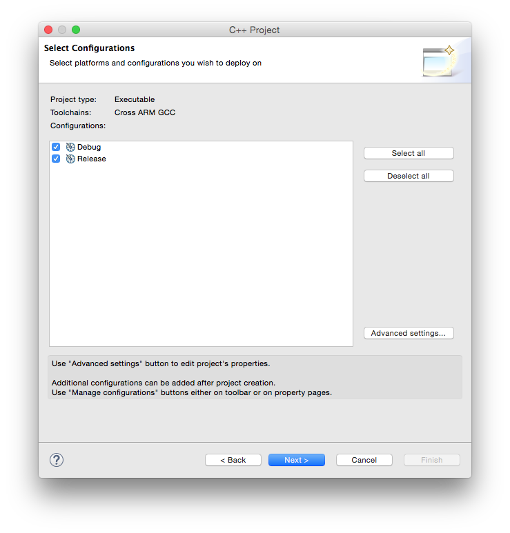
In the Select Configurations page leave the suggested Debug/Release configurations checked and click the Next > button.
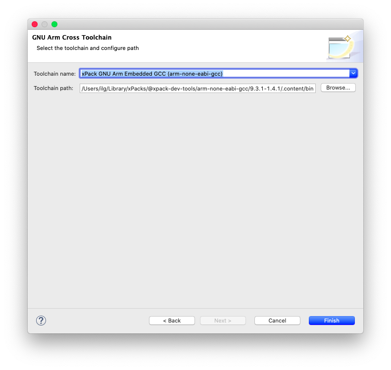
In the Cross GNU Arm Toolchain window:
- select the Toolchain name: xPack GNU Arm Embedded GCC (mandatory)
- if the xPack was installed via xpm, the path is already filled in; otherwise
browse for the
binfolder within the toolchain folder; don’t be afraid to use the absolute path, it is not stored in the project - click the Finish button
/bin folder
where the programs with long, prefixed names are stored, and not the inner
/bin folder where the short name programs may be available.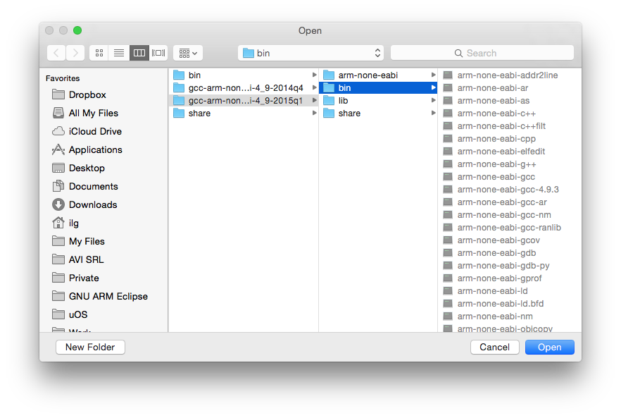
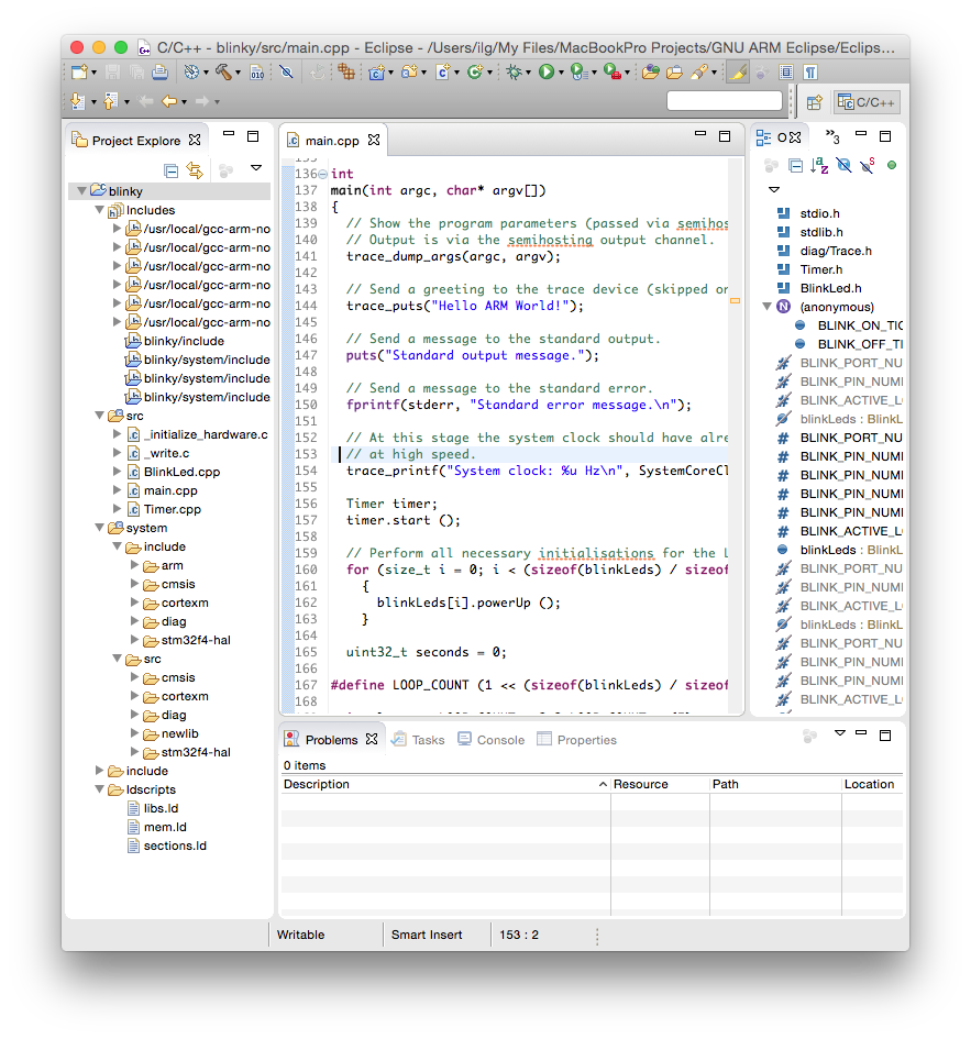
The result of the wizard is a simple project, with a main() function printing a greeting on the standard output.
Build the project
To start the build:
- select the new project in the Project Explorer section
- click the hammer icon
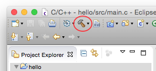
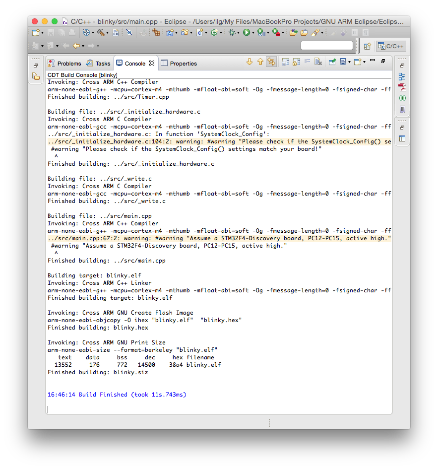
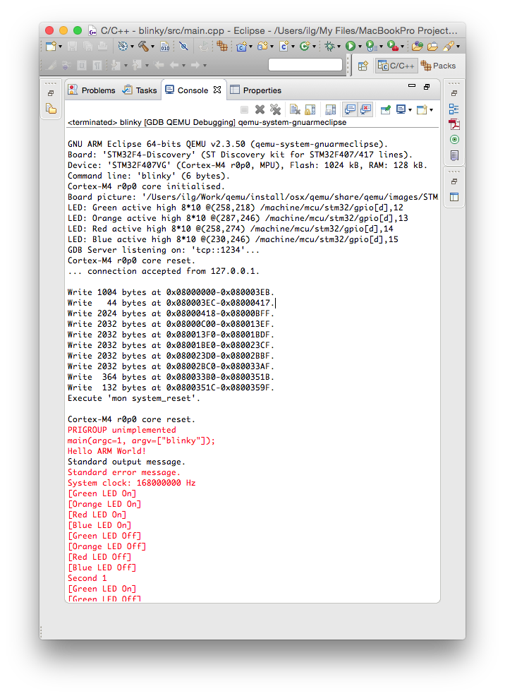
The build process should leave in the Console window a listing like this:
The files created by the build process are left in a folder named by the name of the configuration, for example Debug or Release.
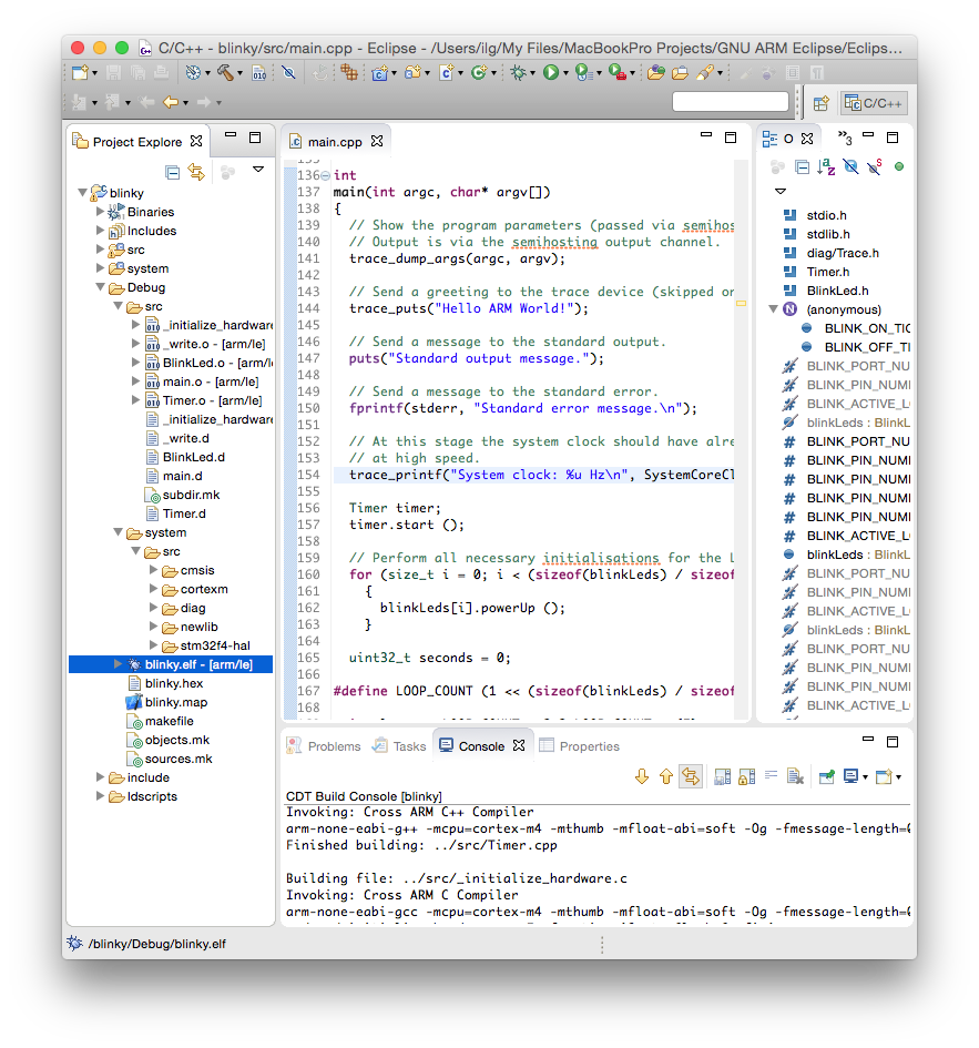
As seen above, the Debug folder is populated with:
- all make files required for the build (makefile and various *.mk files, generated by CDT),
- the object files and dependency files generated during the build (main.o and main.d) and
- the final executable file, with all debug symbols, useful for a debug session (blinky.elf)
- the binary executable file, ready to be programmed in flash (blinky.hex)
- a program map, with all symbols and their associated addresses (blinky.map)
Assign a board and a device to the project
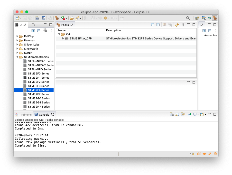
Although optional, it is highly recommended to assign a board and a device to the project, using the packs definitions. If you did not do it before, install the STM32F4xx_DFP package, as explained in the Packs Manager page.
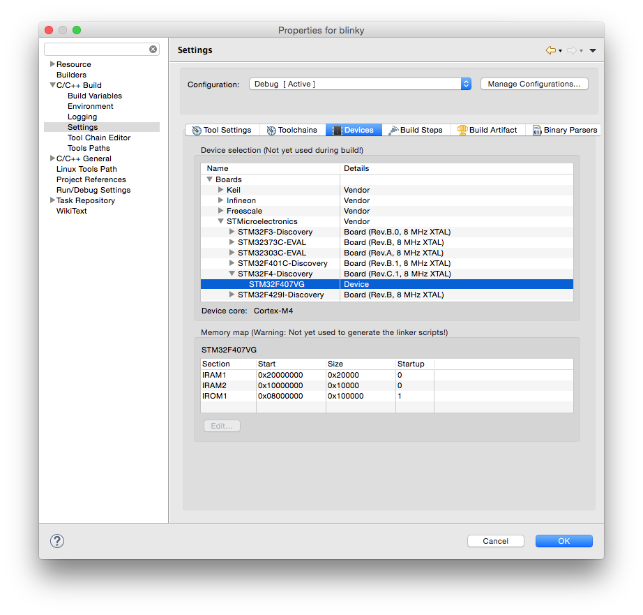
To assign the board and device:
- select the project
- either with right click or via Project menu, enter Properties
- expand the C/C++ Build entry
- select the Settings entry
- select the Devices tab
- in the Boards section, expand STMicroelectronics
- expand STM32F4-Discovery
- select STM32F407VG
- click OK
Debug the test using QEMU Arm
The most convenient way to run a debug session with this test is to use the QEMU Debugging plug-in; you don’t need any physical hardware.
As for any debugging plug-in,
- select the blinky.elf file
- either with right click Debug As… or in the Debug menu, select Debug Configurations
- double click the GDB QEMU Debugging
- select the Debugger tab
- check if the Board name: and Device name: are correctly filled-in; without assigning the board and device to the project, these fields must be filled in manually;
- enable Extra verbose
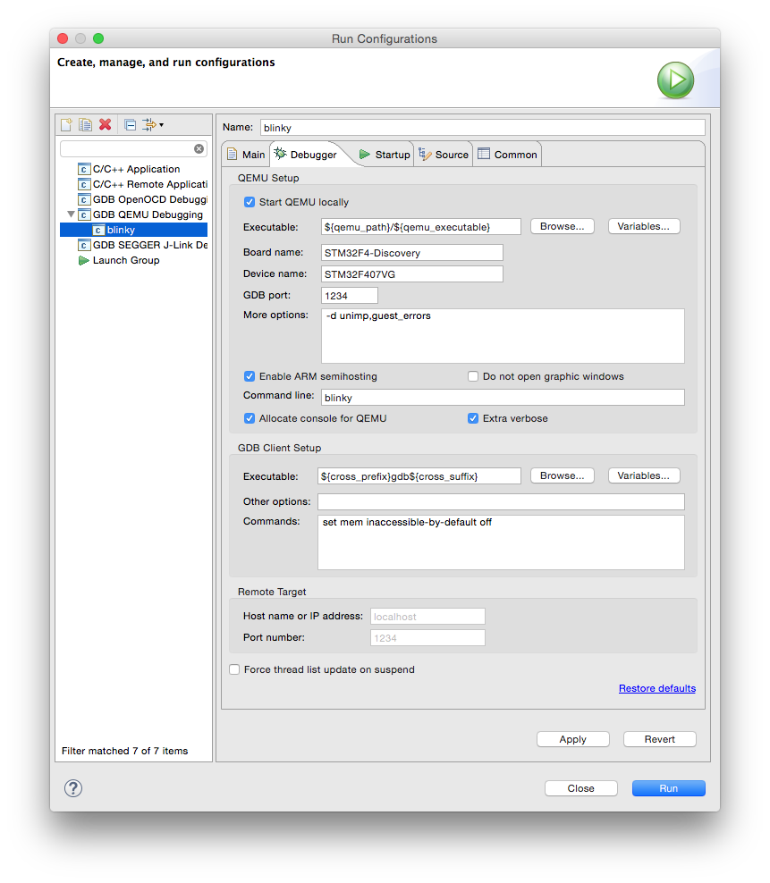
When done, click the Debug button.
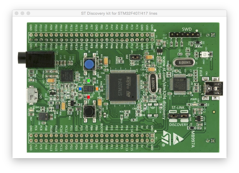
If you did not disable the graphic windows, an animated image of the board is shown, with the 4 LEDs blinking.
The Eclipse debugger is active, with a breakpoint in main(). From here you
can either step over several instructions, or click Resume
(the green right pointing triangle) and watch the program run.
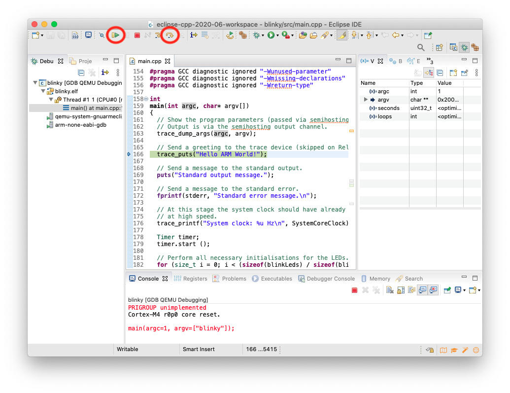
The QEMU process will display some information in its console:
Terminate
The test will run for about 20 seconds, and terminate by itself.
To cancel it earlier, click the Terminate button (the top red square).
Semihosting
Contrary to usual POSIX environments, like GNU/Linux, embedded systems
usually do not provide standard input/output devices. In the code generated
by the template, the output of the printf() calls, including
trace_printf(),
is redirected to a special debugging channel implemented by most debuggers,
using the semihosting protocol.
Next step
Once you checked the development environment to be functional, proceed with creating real projects using the STM32Fx templates, Freescale KLxx templates, or, if your target processor is not yet supported, using the Generic Cortex-M template.
Troubleshooting
The usual sources for build failures are:
- a wrong or missing toolchain path; go to the project Properties → C/C++ Build → Settings → the Toolchains tab and define the correct path;
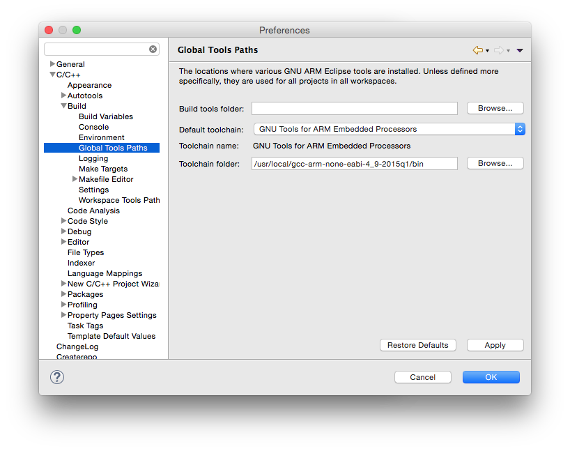
Set the toolchain path for all projects and workspaces.
- missing build tools (make & rm) on Windows; install the build tools;
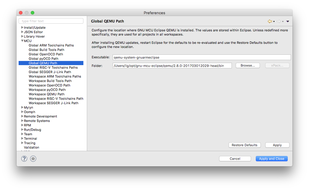
- a wrong or missing QEMU path; go to the project (Window →) Preferences → MCU → Global QEMU Path (or Workspace QEMU Path) and define the correct path;
Support
If you encounter any problems when using this template, please refer to the Support page and do not send private emails.